Bryan Bros meets Bryan Windmills
After erecting the Windmill which sounds a lot easier than it really is. The hard part about it other than just having a big bulky structure to carefully put in place and adjust its position, is adjusting its position to within millimetres. The top and centre of the windmill where the mast sits has to be perfectly plumb so after numerous adjustments the concrete was finally poured the last checks were made and now its set in concrete.
This step of the build was to fit the pump and associated gear. This is where I had to make old meet new, and as I was missing one of the critical parts of this process it gave me an excuse to use the slightly more modern style. This of course came with its own problems as the new part was not designed to have the furling chain or in my case wire rope come out the centre of the push rod.
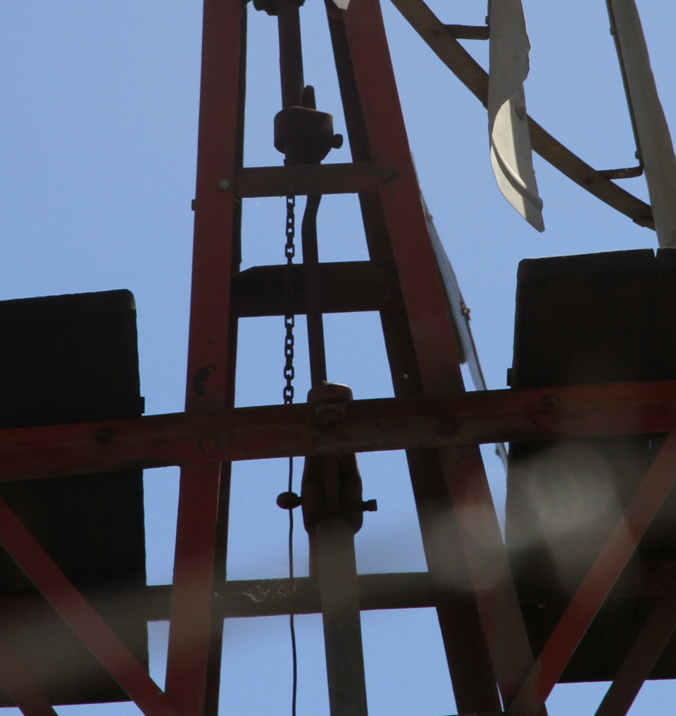
This is the old type of swivel and as you can see the chain coming from the centre of the push rod then joining what looks like a piece of fencing wire.
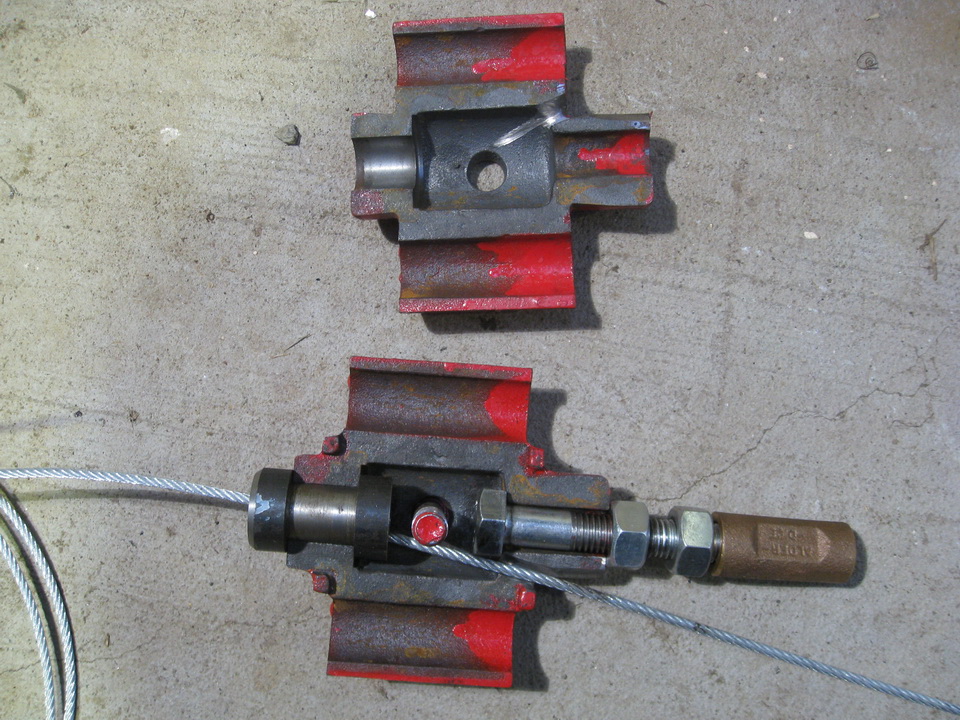
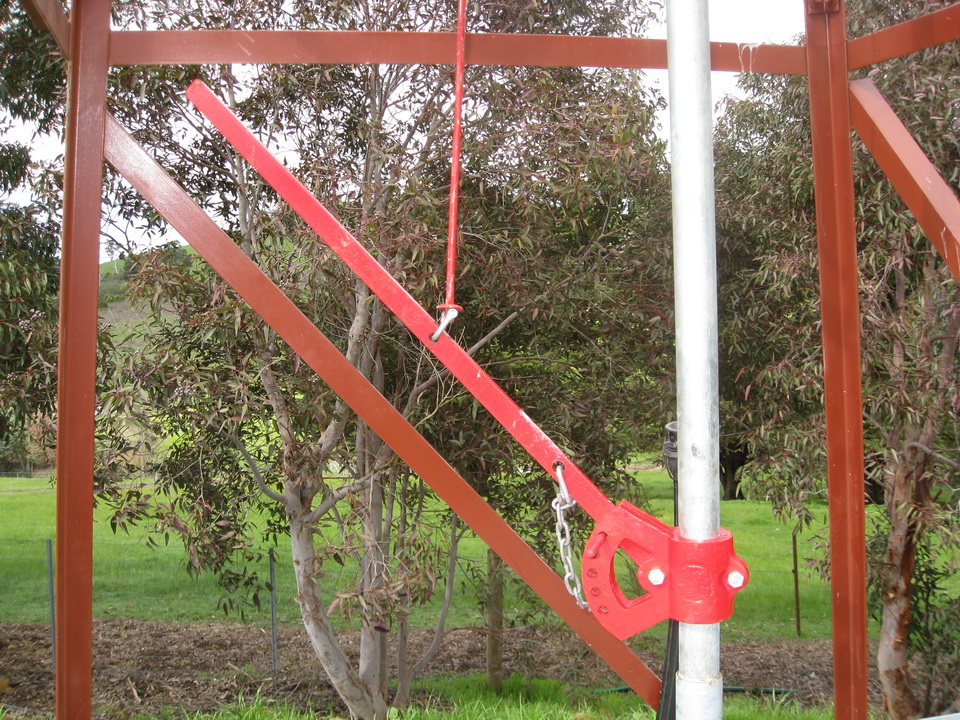
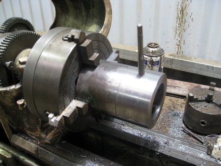
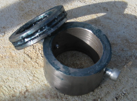
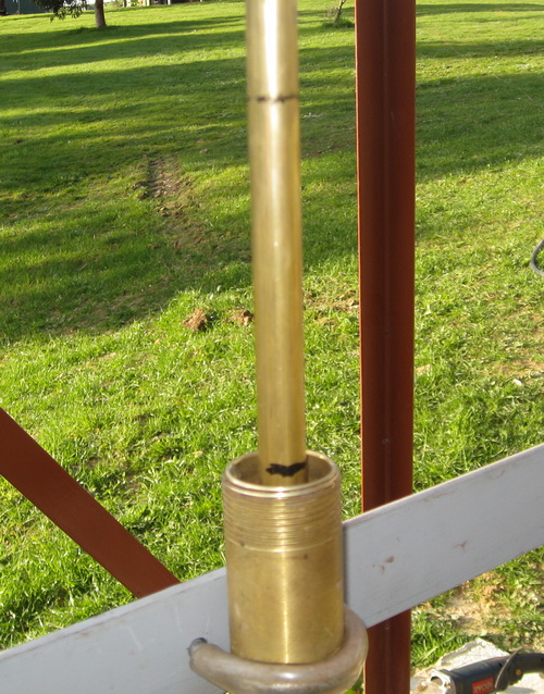
Above is one of the swivels of today at the left side of the picture you can see a small piece of steel this is what does the swivelling this part would be fitted to the pushrod of the windmill gearbox. In my case I welded this to the push rod. First however I carefully machined a bevel on the inside to accommodate the steel rope. To the right of the picture this brass fitting screws into the push rod that activates the pump. As you can see their are two wings to the fitting these travel up and down two guide rods to prevent everything other than the first part I mentioned from turning, and to make sure it runs true. These two rods are connected to what is called the bottom plate. In my windmill I already had one of these (bottom plates) however it was a bit smaller than the new one so I simply fitted a second bottom plate. As you can also see I had to slightly modify the swivel to allow the furling steel rope to exit the centre of the upper pushrod and then after a connecting the steel rope to a small swivel like you use in a fishing lure it connects to the old fixed rod that attaches to the hand lever to turn off the windmill if desired.
When I was talking to Peter at Bryan Windmills about how to assemble all this new gear and how I could integrate it with the old he asked me what I had to hold the windmill down, I replied nothing that thing weighs a ton (in reality it is probably a 100 kgs) wasn't this all that was needed the answer was a "no". That night I slept on it and realised it is a very important part as per Newtons Law when pumping water to a 30m head you have all the weight of that 30m of water to push against so the upwards pressure of the push rod is heaps to say the least. So thanks to Peter I averted a potential problem of having the windmill lift straight up and off from the frame. To overcome this problem I machined up a fitting that would sit below another thrust washer that would sit below the bottom plate. To stop the mast and hence the gearbox from moving upwards.
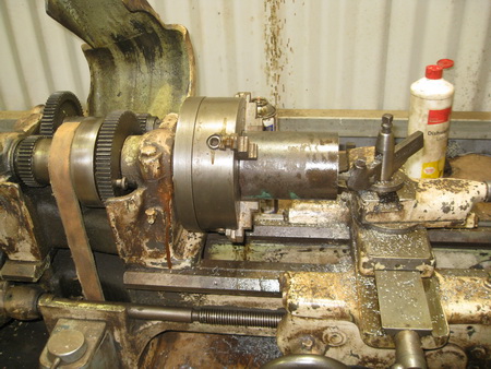
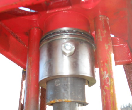
The hex bolts once tightened evenly to hold everything securely had their heads cut off flush with the fitting so that it could rotate freely between the two guide rods.
From this point I started to work from the bottom as I could now use the push rod as a plumb line. To do this I fitted the a pipe to the bottom cross braces before the brace was welded to the tower frame. I could then move this brace so that the push rod was exactly in the centre of the pipe. The brace was then welded in place. I then fitted the pump which had this same pipe at the bottom. So with the bottom now centred. I cut the push rod off slightly still not to the exact length. I followed the same procedure with the top of the pump. I connected the pump top to a brace and then moved this brace until the push rod of the pump was exactly inline and under the push rod hanging from the top swivel.
I now measured or at least rechecked the windmills stroke and the pumps stroke, and calculated that the pump had about 50mm each end free space which is perfect as you don't want the pump hitting either end when in operation.
I made these markings on the pumps push rod and then set the windmill to one of its extremities of its stroke and matched the pump accordingly taking into account the fitting that would go between them and then I cut the push rod hanging down to length.
I then removed the push rod and tapped the end of it with a thread so the brass fitting adapter could be placed between the two. A milestone had arrived I put the windmill into action briefly to make sure the travel was as per the two lines I had drawn on the pump rod, it was exact. I was relieved.
The next step was to remove the push rod and cut the outer pipe to length and to fit the spreader to just below the bottom of the swivel guide rods. I had to add some extra angle iron to the frame to take the new spreader but it matched up with where the old one was perfectly so just made it wider and stronger.
Now I had to place the push rod inside the guide pipe and firstly hold the guide pipe above the pump rod so I could join two push rods then lower the guide pipe and connect it to the pump. I then connected the two upper push rods together and then adjusted the top spreader (that had not been fixed into place as yet) so that the push rod was in the centre of the guide pipe. I then fixed the spreader into place.
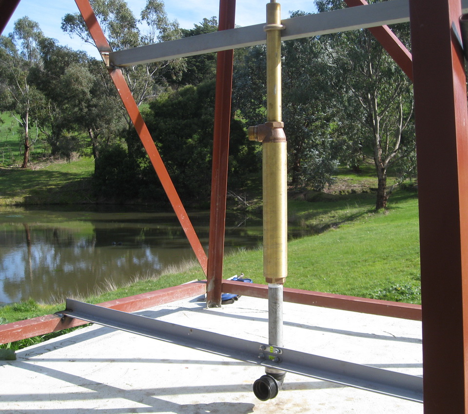
All that was left now was the plumbing.
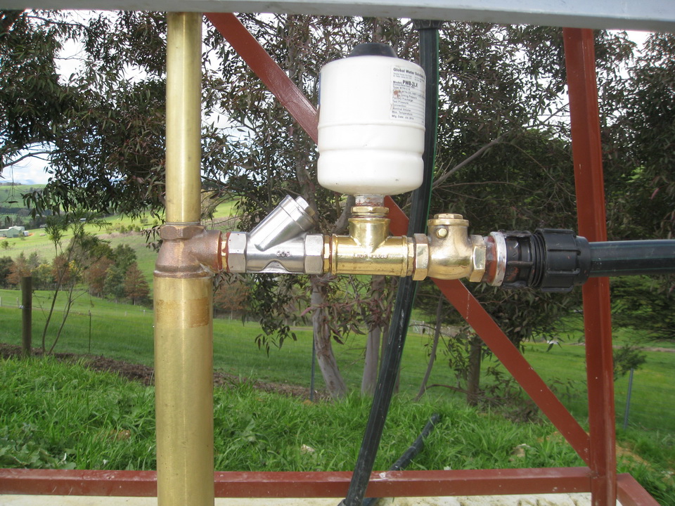
To start I put in the suction line the end that was in the dam had a float and a non return valve fitted I also put a T section in line just before the pump so that I could fill this and prime the pump water would always remain in this section of pipe keeping the pump constantly primed and ready to go.
On the output side I placed a air tank to even out any pulsating that may occur but given the distance and the head to the tank and the fact the pipe was buried it was probably unnecessary, but at this stage I wasn't in the mood for any problems. Peter also assured me that I really only needed one non return valve on the output of the pump but I had seen so many pictures with two valves and I could not find an answer to this after exhaustive research on the net, so again I went with the more is better theory.
The last thing to fit off was the hand lever and adjust the steel rope so that it was free with little or no pressure on it when in the up position and off or furled when lowered which only takes two notches on the handle