Bryan Windmill Restoration
The restoration followed the same procedure as any restoration. First take it all apart, clean it up, replace or repair any worn or broken parts and give it a new coat of paint. This is a brief rundown of what was done. There were many times that I did something and then wished I had taken a photo of it in its original state, but that's how it goes, sometimes you get so involved, you just concentrate on the job.
Once I had the gearbox apart I put the parts in a light acid wash to clean them up and remove any rust. There was an inch thick of gunge on the bottom of the gearbox from old oil. This was washed out and cleaned in a bath of diesel fuel. After the acid wash the parts got a clean up with the wire brush, sandpaper, or a grinding disc.
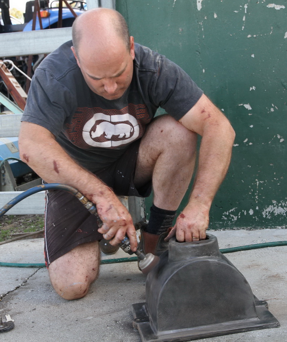
After they had been cleaned up I gave them a coat of paint with an industrial strength anti rust paint combination. First was an undercoat / primer then several coats of top colour, luckily the original colour was red which looks great so that what all the parts got.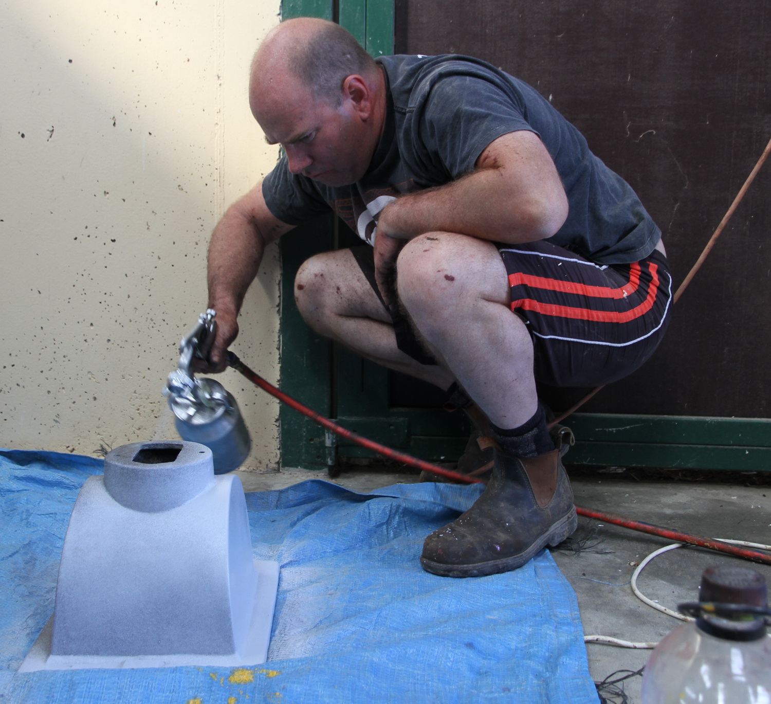
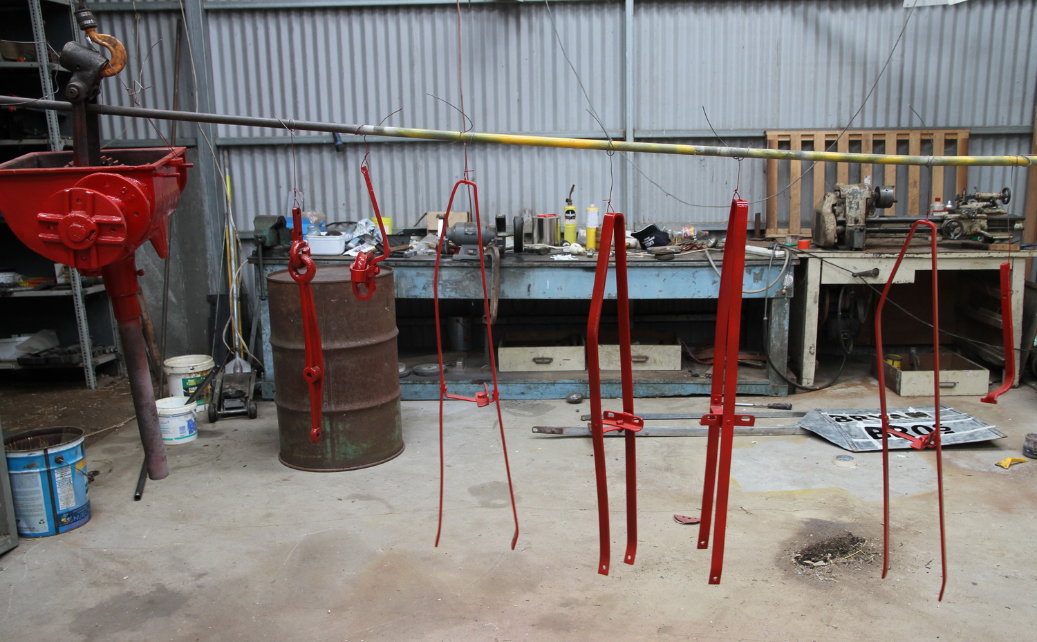
From top to bottom inside and out parts were given some attention.
The top Bearing which the gearbox sits on was well ? I only had half of the casings and no ball bearings not that I think they could have been reused.
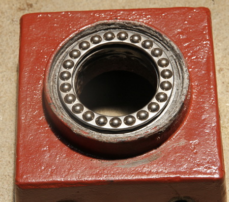
It used to be a cast top and bottom with loose ball bearings sitting in the races.
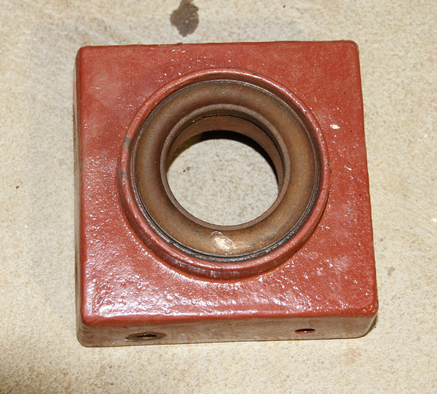
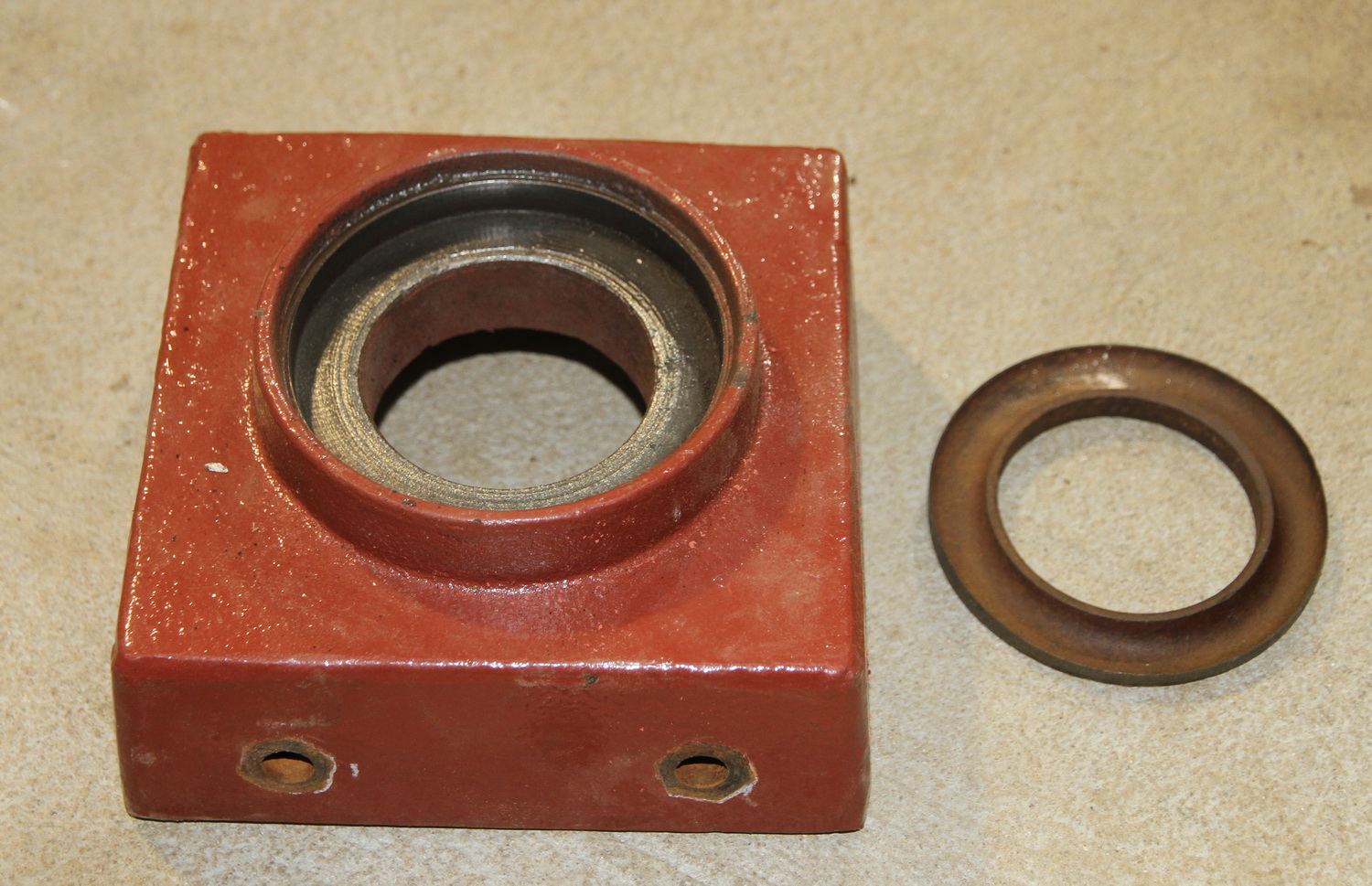
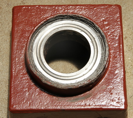
This old type bearing I replaced with a new thrust bearing. Of coarse it was not the exact push fit size. The original was probably hand made individually to fit the other cast and machined part. So what I had to do was centre the new thrust bearing and then I liquid steel filler around the bearing to hold it in place. The new bearing is a high grade machined steel and rotates very freely.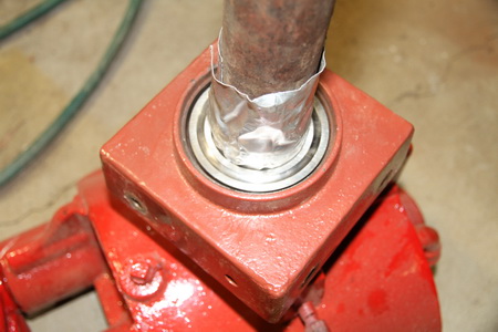
 Because the old bearing had probably failed while in operation and not been replaced at the time and the windmill was continued to be operated it caused some flow on effects wearing parts unevenly and damaging them.
The failure of the bearing caused the mast to operate at an angle. This out of plumb condition caused excessive wear on the lower part of the mast pipe both on the inside and outside as can be seen in the pictures below.
In fact the failure of this bearing is probably what lead the windmill to its ultimately catastrophic failure as the fan would now of been operating at an angle and hitting the windmill tower. This would have bent the vanes of the fan and perhaps stopped the wheel altogether.
There were signs that the windmill had fallen over at some stage as evidence of the fan being so damaged and out of round. However falling over may have happened when they where dismantling it. 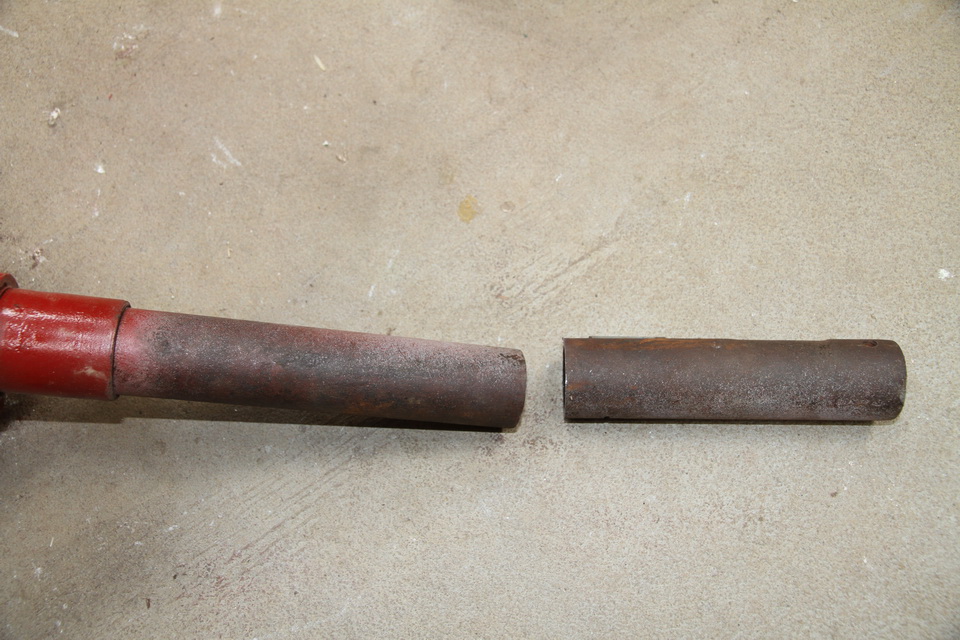
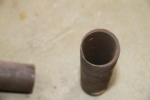
To repair the mast pipe on the gearbox I cut the worn section out, fortunately this size of pipe is still available today and I was able to then weld a new section in. To perform the weld I had to use some other pieces of U section steel that I could clamp to the pipe to ensure a nice square and straight joint. I could of just replaced the complete pipe however I really wanted to maintain as much of the original parts as I could that were practical to use again.
When cleaning the mast pipe up I found this logo on the pipe I don't know what company it refers to. If someone out there knows please send an email and let me know, It would be greatly appreciated. There are still some uncovered stories and mysteries with this windmill.
![]()
The next part that I had to make because it was missing was the tail vane support. I didn't take any pictures of this unfortunately, I didn't think of it until it was too late and assembled. This took me a long time to work out exactly what was down there under the gearbox to achieve this function. In the end I just used a solid block of 50mm by 50mm piece of steel cut to the correct size. The size was important though as it only had one hole to attach to the gearbox and it relied on being the correct length so as not to rotate. It had another hole drilled on the 90 degree side for the axle to sit in the other end of the axle was fitted to the gearbox. The axle was for the tail vane to connect to. This block had to be shaped so I shaped it with the grinder and grinding wheel to how I thought it needed to be, to operate correctly. To determine the shape I spent some lengthy time looking at a picture I had taken at Theo Cooks Windmill Park in Shepparton and doing a lot of reading about how the tail vane actually furled in strong winds.
It is a very simple yet clever design the fan is offset to the tail vane. When there is a lot of pressure pushing on the fan this becomes greater then the pressure on the tail vane holding it into the wind and cause's the fan to fold into the vane and move away from the direction of the wind. For the tail vane to rotate however it doen not to so on a completely horizontal axis and has to raise up as it furls. Thus the gravity on the tail vane restores it to a straight position when the wind pressure on the fan decreases.
For this to happen the block holding the tail vane has to allow the tail vane to rise as it rotates as does the hole in the tail vane attachment.